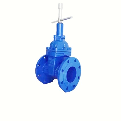
Structure and working principle of mechanical triangular lock gate valve
Release Time:
Aug 04,2025
The essence of mechanical triangle lock gate valve is to integrate a high reliability mechanical interlocking system on standard industrial gate valves. The core principle is to use a dedicated key to synchronize the physical locking of the valve stem, operating handwheel (or gearbox), and protective lock cover through a precise linkage mechanism. This design maximizes the prevention of unauthorized operation or disassembly, providing strong, intuitive, and compliant physical security for industrial process isolation. It is an ideal hardware support for the "lock and tag out" program. Its structure is sturdy, the operation is clear (lock/unlock status is clear), and the safety redundancy is high (multiple points are locked simultaneously), making it one of the key valve types to ensure the safety of personnel and equipment in high-risk industrial environments.

Mechanical triangle lock device: This is the core part that distinguishes it from ordinary gate valves, usually installed on the top of the valve cover or at the position of the valve stem nut. Its main components include:
Lock cover: a protective metal casing that wraps around the top of the valve stem and the lock cylinder mechanism. Lock covers are usually designed to require a dedicated key to open or remove.
Lock core mechanism: the core component located inside the lock cover. contain:
Specialized lock cylinder: typically a high security mechanical lock (which may be a pin lock, blade lock, or a higher security level design) that can only be operated with a specific, unique (or limited authorization) key.
Linkage mechanism: a precise set of connecting rods, gears, or cam systems that simultaneously transmit the rotational motion of the lock cylinder to multiple locking points.
Locking point/tongue: a component driven by a linkage mechanism, used to physically block the operation or disassembly of valves. The key "triangle" characteristic is reflected in its usual simultaneous locking of three key points:
Valve stem locking: One or more locking tongues extend into specially designed grooves or holes on the valve stem, directly locking the valve stem and preventing it from rotating or lifting (depending on the valve type).
Handwheel locking: The linkage mechanism simultaneously drives a locking tongue or buckle, which is inserted between the spokes of the handwheel or into a specific locking hole to prevent the handwheel from rotating.
Lock cover/valve cover locking: The linkage mechanism also drives a lock tongue or bolt to firmly lock the lock cover itself on the valve cover or valve body, preventing the lock cover from being removed without authorization (thus also preventing contact with the valve stem nut for disassembly). Sometimes this locking point is also designed to prevent the valve cover bolts from loosening.
Working principle
Locked state (valve closed and locked):
After the valve is closed, the operator inserts a unique dedicated key into the lock cylinder.
Turn the key (usually clockwise or counterclockwise at a specific angle, such as 90 degrees or 180 degrees).
The key drives the lock cylinder to rotate.
Unlocked state (valve operable):
Authorized personnel insert the dedicated key into the lock cylinder.
Turn the key in the opposite direction.
The key drives the lock cylinder to rotate in the opposite direction.


